ZenBot
Summary of a team project and detail description of its mechanical hardware
I looked forward to a team project from the start of this semester. The project we took on with my fellow students was combining many skills both from this subject and outside it. I believe that no single person would be able to do such a masterfull work alone, as we did in just a short span of two weeks. Let me show you ZenBot!
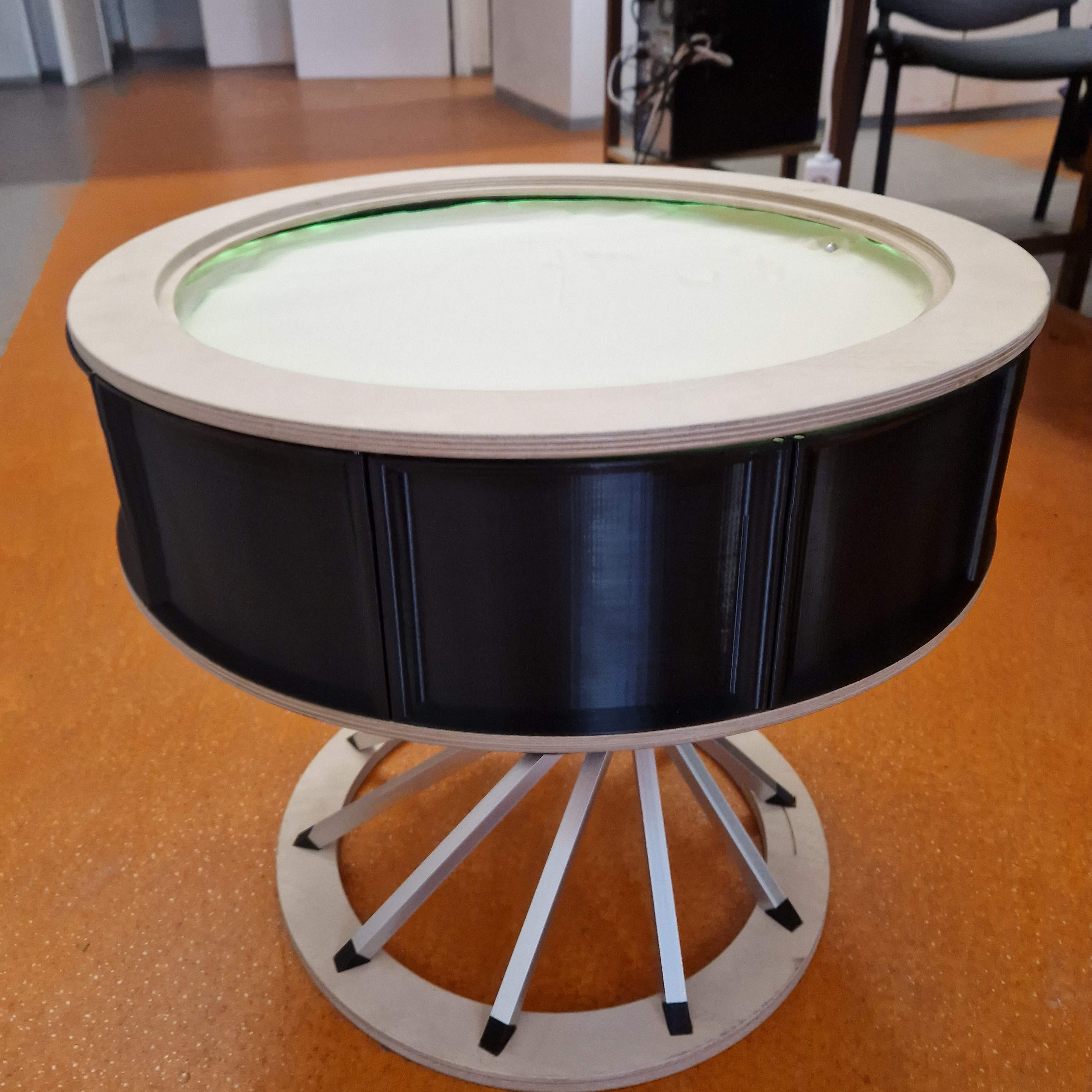
ZenBot is a machine hidden inside a beautiful piece of furniture. A coffee table with a sand-drawing mechanism inside. Its base stand and bottom and top rings are made from plywood. Legs are aluminium and curved and connecting parts are 3D printed from PETG. The sand drawing itself is happening in a chamber sealed from the top by glass, which makes the table top. The floor of this chamber is a plexi glass under which sits the drawing mechanism. Its made up from a SCARA arm system, driven by two stepper motors. The whole machine is controled by a Raspberry Pi and powered by a single stable source. The arm has a strong neodymium magnet at its tip to control a steel ball inside the sand chamber. Through out the design of ZenBot you can see intention to make it simple and clean from the ouside while keeping the complex mechanism hiden and leaving just the mesmerising sand-rolling ball and intriguing design to catch users attention.
SCARA
I will be describing the internals of ZenBot mostly, since that was my main focus in our team.
Used tools, methods and technologies:
- 3D printing, laser, soldering
- CAD and basic electronics
- Neodymium magnets
3D Model
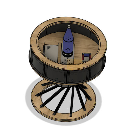
The arm mechanism, even though hidden from plain sight, is a defining part of the machine. Its height has to be minimized while range of operation maximized. That determines minimal dimensions of the table and naturaly we wanted a big working area for the sand-plotting to take place.

It took many interations of the design. The first prototype we did with John, see his page here final project. My second version was working quite well right from the first print, but it was bulky, too hight and tolerances were off. Thanks to precise and parametric CAD, I needed just time to figure out where height could be shaved and how everything fits together. The only issue was with motor axes, which in reality extended higher then in my model and caused jamming of the arm whenever it was above it. Otherwise, the thrid version was a success.

SCARA arm inside the table. Section analysis. Green parts are the connecting ones, orange are wood, red are the belt wheels. Pink at the tip is the magnet block.

Most of the arm is made from white PLA and printed on Prusa MK3S or BambuLab Mini A1. Some parts are PETG. The longest parts of the are cut from a firm 4mm plywood. Many specific nuts and bolts hold the whole contraption together. Belts were cut and soldered afterwards so that they would fit precisely. This was however a mistake, because connecting the belts reliably proved to be very hard. I would definitely go for a bought ones and then incorporated some belt tesioning into the design.

I was able to shave of a lot of height inserting components into the spinning belt wheels. One of my teammates had an idea to drill pockets into bottom part of the table and lower the motors, lowest part of the SCARA into them. It worked great and combined, these two with some smaller impovements reduced the height by 30mm. Thats a lot. The height of the final arm toghets with magnets on top is just over 120 mm and putting motors lower in the base made the tip only 110 mm above the base.